How Packed Bed Scrubbers Work: A Practical Engineer's Breakdown
What every engineer specifying a wet scrubber system needs to know about packing media, liquid distribution, mist elimination, and controls before the equipment ships.
Summary
A packed bed wet scrubber removes corrosive gases, vapors, and fumes from industrial exhaust air by forcing contaminated airflow through a column of packing media continuously wetted by a recirculating scrubbing solution. A system that's correctly specified hits its removal targets for years; one that isn't creates compliance exposure and maintenance costs that compound quietly until they don't. Understanding the mechanics behind each component — packing media, liquid distribution, mist elimination, and controls — is what separates a well-specified system from one that underperforms from day one.A packed bed wet scrubber running at 80% removal efficiency looks exactly like one running at 99%. The gauges are turning, the pump is recirculating, the air is moving. The difference shows up in an air quality exceedance, a permit violation, or a corrosion problem downstream that took months to trace back to a scrubber that was never quite doing its job.
Most of the time, the failure wasn't in the equipment but the specification.
This is a component-level breakdown of how packed bed wet scrubbers work, what each part is doing, and what an informed practitioner needs to understand to evaluate a system specification before it becomes a field problem.
Key Takeaways
- Mass transfer drives everything. Packed bed wet scrubbers capture corrosive gases through the movement of contaminants from the gas phase into a continuously recirculated scrubbing liquid across a high-surface-area packing column.
- Packing media geometry is not incidental. Well-designed random packing eliminates channeling, keeps all surfaces wetted, and maintains the low pressure drop needed to keep air moving through the column at 400–600 FPM.
- Orientation matches the application. Vertical (counter-current) scrubbers maximize removal efficiency for a given packing depth and suit high-efficiency applications like semiconductor fabs, wastewater treatment, and plating lines; horizontal (cross-flow) scrubbers offer lower pressure drop and easier installation in space-constrained facilities.
- Recirculation chemistry management is not optional equipment. A system with dissolved solids accumulating unchecked can show normal operating indicators while delivering well below its rated removal efficiency.
- The mist eliminator is application-specific. Blade type and configuration determine which droplet sizes are captured, and leaving contaminant-laden moisture in the exit air stream defeats the scrubber entirely.
The Core Mechanism: What ‘Mass Transfer’ Means
A packed bed scrubber is an air pollution control device. Contaminated air enters the system, passes through a media-filled contact zone where it meets a scrubbing liquid, and exits as cleaned air. The scrubbing liquid captures or reacts with the contaminants. The cleaned air moves on.
Mass transfer is the technical term for that exchange, the point where a contaminant molecule moves from the gas phase into the liquid phase. The rate of mass transfer is what drives removal efficiency. The more contact surface and contact time, the more complete the transfer.
Packing media exists for one reason: to multiply that contact surface area without creating so much resistance that you can't move air through the column.
Inside the Packing Column
The packing section is the engine of a wet scrubber. It's filled with loose-fill media — typically polypropylene in shapes like Jaeger Tri-Packs®, Lantec Lanpac®, or Rauschert — engineered specifically to maximize wetted surface area while minimizing airflow resistance.
What makes these media work is the combination of high active surface area and high void fraction. The scrubbing liquid cascades down through the column and wets the packing. The contaminated air moves up (or across, depending on orientation). Every wetted surface becomes a contact site for mass transfer.
Channeling kills scrubber efficiency. When packing nests or clumps, dry pockets form. Contaminants pass through those pockets without making contact with the liquid. Well-designed random packing (geometrically consistent, structurally uniform) eliminates nesting so every surface stays wetted. That geometric uniformity is what distinguishes engineered media from generic fill material.
Air velocity through the packing section typically runs 400–600 FPM. Drop below that range, and you lose the turbulence that drives gas-liquid contact. Exceed it, and you risk flooding the column — liquid can't drain against the airflow. Staying in the design window matters.
Packing depth sets how much contact time the gas gets with the liquid. Standard depth in most industrial wet scrubber applications runs 60 inches. Applications requiring higher removal efficiency typically specify 72 inches, which increases both contact time and pressure drop. The tradeoff is real: more depth means more fan horsepower to move air through the system.
Vertical vs. Horizontal: Orientation Isn't Incidental
Packed bed scrubbers come in two primary configurations, and the choice between them isn't merely cosmetic.
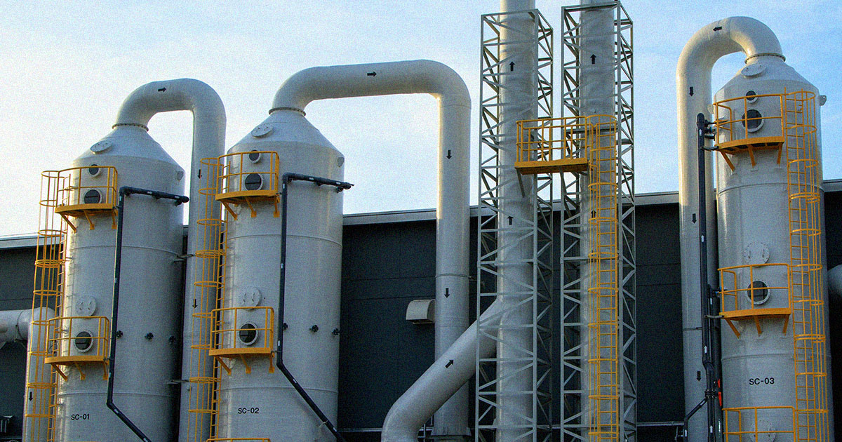
Vertical (counter-current flow): Air enters at the bottom and moves upward through the packing. Scrubbing liquid enters at the top and flows downward — directly opposing the gas flow. Counter-current contact maximizes the concentration gradient between gas and liquid throughout the column, which produces the highest removal efficiency for a given packing depth.
Vertical scrubbers are the standard choice for high-efficiency applications: acid gas control in semiconductor fabrication facilities, corrosive fume abatement on plating and anodizing lines, and ammonia removal in wastewater treatment. If your application has a strict removal target and enough overhead clearance to accommodate the tower height, this is the configuration to specify. The footprint is compact; the height is the tradeoff.
Horizontal (cross-flow): Air moves horizontally across the packing while liquid flows downward through it. The gas and liquid paths are perpendicular rather than opposing. This geometry produces lower pressure drop compared to counter-current designs, which is the reason to choose it.
Facilities with limited overhead clearance specify horizontal units for exactly that reason: indoor chemical processing areas with low ceilings, equipment rooms where vertical height is simply not available, retrofit applications where the scrubber has to fit within an existing structural envelope. Maintenance access is also generally easier. The efficiency ceiling per foot of packing is lower than counter-current, but for many applications the target removal rate is achievable within the cross-flow design, and the installation advantages are decisive.
Both configurations rely on the same fundamental packing media and recirculation mechanics. The geometry changes; the mass transfer principles don't.
The Recirculation System
The scrubbing liquid doesn't just appear at the top of the packing column. A pump draws liquid from a sump at the base of the scrubber and delivers it upward through a spray header or weir trough system that distributes it evenly across the full packing cross-section. From there, gravity does the rest. The liquid cascades through the media and returns to the sump for recirculation.
Recirculation rates typically run 2–15 GPM per square foot of open packing area, with 4 GPM per square foot as the standard design point for most industrial applications. That rate sets how much liquid is available to wet the packing at any moment. Too low and dry zones appear; too high and pressure drop climbs.
pH and conductivity sensors in the sump monitor solution chemistry in real time. A pH controller triggers chemical dosing to maintain the scrubbing reaction at peak effectiveness. A conductivity controller manages total dissolved solids by triggering blowdown — draining a portion of the saturated recirculation water and replacing it with fresh makeup water. Without blowdown management, dissolved solids accumulate until the solution can no longer absorb contaminants. The system looks like it's running. It's not removing much. From there, rising conductivity readings will tell you what's happening if you're watching them, which is exactly why the instrumentation isn't optional.
Pump redundancy is a design decision with real operational consequences. A single pump failure in an active scrubber system can mean unplanned downtime in a process that generates corrosive exhaust, regardless of whether the control equipment is functioning.
The Mist Eliminator: The Last Line of Defense
Saturated air leaving the packing section carries moisture droplets. Those droplets contain whatever is dissolved in the scrubbing solution, which is to say, the contaminants the scrubber just collected. If that moisture exits with the air stream, it defeats the purpose of the scrubber and creates a secondary contamination problem downstream.
The mist eliminator sits above the packing section and intercepts those droplets before the air exits. Impingement-type blade designs force the moisture-laden airflow through a series of direction changes; the droplets can't follow the deflections, impact the blade surfaces, coalesce into larger drops, and drain back down into the sump.
Mist eliminator selection depends on the specific droplet sizes you need to capture.
- Horizontal cross-flow blade designs achieve 99% removal of 20-micron droplets.
- Vertical counter-current blade designs reach 99% removal at 32 microns.
- Composite mesh pads push that down to 99% removal of 3-micron droplets for applications requiring finer capture.
Matching the mist eliminator type to the application is part of a complete scrubber specification, not an afterthought.
What a Complete System Specification Requires
A scrubber doesn't start at the packing column and end at the outlet. The components around the packed bed — the controls, the containment, the piping — determine how the system actually performs in service.
To properly size and specify a packed bed wet scrubber, the design engineer needs:
- Inlet gas flow in ACFM
- Inlet loading rate of each contaminant in ppm or pounds per hour
- Gas temperature
- Required removal efficiency
- Indoor or outdoor installation
- Preferred configuration, whether the recirculation system will be self-contained or remote
- Secondary containment requirements
Every one of those inputs affects the design. Missing any of them means the system gets sized on assumptions. And assumptions in air pollution control create compliance exposure.
Secondary containment is worth naming specifically. In systems handling corrosive chemistry, any leak point in the plumbing is a worker safety issue and a potential environmental liability. Containment approaches range from a base pan that captures drainage from the scrubber sump, to full encapsulation — a protective shell built around the entire scrubber plumbing assembly — that catches any leak at any point in the system before it reaches the floor.
Wet scrubbers ranging from 500 CFM to 100,000 CFM fall under this same design framework.
The Factory-to-Field Gap
The spec defines the system on paper. The manufacturer determines what you actually receive on-site.
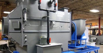
A factory-tested, fully pre-plumbed scrubber (in which all valves, pumps, and sensors are assembled and water-tested before shipment) arrives at the installation site as a verified system. Field installation is faster, startup is cleaner, and the risk of discovering a plumbing problem after the system is commissioned drops significantly.
The alternative is a scrubber body shipped to a job site where the installing contractor handles all plumbing assembly. That introduces variation the spec can't control.
Viron International has been manufacturing complete corrosive air handling systems for over 50 years, serving industries from semiconductor fabrication and wastewater treatment to chemical processing and metal finishing. Our wet scrubbers — vertical, horizontal, and blower-scrubber configurations — are fully pre-plumbed and water-tested before shipment. We manufacture the scrubbers, the FRP and SSTeelcoat® ductwork, and the industrial fans as integrated systems, engineered together.
If you're evaluating a packed bed scrubber for a corrosive exhaust application, contact our engineering team with your process data, and we'll give you a straight read on what the system actually needs. Contact Viron today or request a quote.
Frequently Asked Questions
Can a packed bed scrubber handle multiple contaminants simultaneously?
Yes, but it requires careful chemistry. Different contaminants may require different scrubbing reagents, some neutralized by acid solutions, others by caustic. Running incompatible chemistries in a single-stage packed bed isn't always feasible, however. Applications with mixed contaminant streams often require staged scrubbing (two scrubber sections in series with separate recirculation loops and different solution chemistries) to achieve target removal across all species. This is a design-phase decision, not something to retrofit.
What causes a packed bed scrubber to lose removal efficiency over time?
The two most common causes are packing fouling and chemistry drift. Fouling occurs when particulates or scaling deposit on the packing media, reducing wetted surface area and increasing pressure drop. Chemistry drift happens when blowdown management fails — dissolved solids accumulate in the recirculation loop and the solution loses its capacity to absorb contaminants. Both problems are detectable: fouling shows up as rising differential pressure across the packing section; chemistry drift shows up in conductivity readings. Regular monitoring catches both before they become compliance issues.
What's the difference between a self-contained and a remote recirculation system?
A self-contained unit mounts the recirculation sump and pump directly to the scrubber body — compact, no separate tank required, and the preferred option in warmer climates or indoor installations where freezing isn't a concern. A remote system locates the recirculation tank away from the scrubber body, typically inside a building when the scrubber itself is rooftop-mounted or in a cold-weather region where the sump could freeze. Remote configurations also allow visual monitoring of recirculation flow independent of the scrubber location.
How does packing media material selection factor into the design?
Most industrial scrubbers use polypropylene packing, which handles a broad range of common corrosive chemistries at standard process temperatures. Higher-temperature or more aggressive chemical environments may require CPVC, Kynar (PVDF), or ECTFE (Halar) media. The wrong material choice degrades under the process chemistry, loses its geometric shape, reduces active surface area, and eventually fails. Material compatibility between the scrubbing solution and the packing is a specification decision that should be made before the equipment is ordered, not discovered during operation.
How do I know whether my process chemistry requires FRP versus PVC scrubber construction?
The short answer is temperature and chemical aggressiveness. PVC handles a workable range of corrosive chemistries at moderate temperatures and is a cost-effective choice where those conditions apply. FRP with a vinyl ester resin inner corrosion barrier handles a broader spectrum of acids, alkalis, and organic compounds, and extends the operating temperature ceiling significantly. The more important point: if the housing degrades (blistering, delamination, cracking) you're looking at a structural failure in a vessel under continuous recirculation of corrosive solution. Housing material selection should account for the full range of chemistry the unit will see, including any upset or off-spec conditions, not just normal operating parameters.